This combination provides better overall mixing and creates a higher oxygen mass transfer rate K L a than that of unidirectional marine blade impellers. Impeller design Impeller can be classified to axial radial and helical according to shape of disk that attached to impeller shaft.

Axial Flow Impeller Pitched Blade Turbine 3d Cad Model Library Grabcad
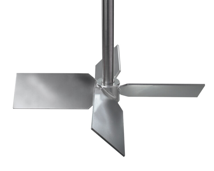
The image below illustrates basic impeller operation.

. Viscosity of up to 25000cP. This impeller is suitable for low viscosity. Impeller design data includes impeller dimensions number of blades turbulent power number turbulent flow number and impeller synonyms.
Impellers consist of various vanes often blade-shaped arranged around a short central shaft. Each reactor configuration was simulated at different revolution speeds such as 10 20 50 and 100 RPM. As the first evolution of the flat blade turbine the Pitched Blade Turbine or PBT was designed to angle the blades to promote more axial flow than radial.
Figure 3 shows the relationship 2 for a 45 pitched blade turbine PBT. Pitched Blade Diameter 79 mm. A radial flow impeller provides primarily a side to side flow pattern in a baffled tank.
Typical applications include placement of the impeller close to the bottom of a tank for sweeping vessel floor. 4c and 8 Pitched cylindrical three-blade turbine according to Czech standard CVS 69 10422. Pitched blade impeller for effect ive stirring operation in the fluid tank.
Up to 24 cash back Agitator Design Mech Spreadsheet. The horizontal circulation is the main flow and at high speed the radial flow is main. If you cant find your impeller design here see if it is stored under Special Impellers.
Np Graph and User Guide will be provided along with spreadsheet. Depending on the angle of the blade pitch 45 degrees being the most common the impeller axial to radial flow ratio can be tuned for the specific process. Pitched Blade Turbines Though the traditional Pitched Blade Turbine is a good all-purpose impeller for a wide range of applications Brawn has refined the standard design through testing with varied pitch angles blade width and other adjustments by application.
The design of the PBT impeller provides a combination of both radial and axial flow generates higher shear levels for reactions and provides excellent mixing ability while providing easy cleanup. Impellers suitable for viscous fluids are. A a radial flow Rushton turbine which produces considerable turbulence near the impeller b a pitched blade impeller with flat angled blades that generates a diverging but generally axial flow c a hydrofoil impeller with carefully profiled blades that develop a strong more truly axial flow of low turbulence.
At first the pitched-blade turbine Figure 2 was used as an upper impeller. The Pitch Blade Turbine impeller is one of the most widely used impellers and one of the oldest designs of the mixing industry. Widely used for suspension dispersion and homogenization processes.
The entrainment depends on the mixer. Standard pitched six-blade turbine with pitch angle α 45 Pitched blade turbine with diagonally folded blades with various blade number iL 3 4 and 6 blade shape of this impeller type according to Czech standard CVS 69 1043 see Figs. Download scientific diagram Pitched blade impeller vortex.
Pitched blade impeller design Written By julianschonaerts1168 Sunday March 27 2022 Add Comment Edit. Equipped with 4 blades this high shear mixer is replaced by impeller in many fields. Pitched-Blade Impellers for Shear-Sensitive Cells.
A nutrient rich medium is continuously fed into the reactor and products are harvested. The blades on pitched-blade impellers Figure 3 are flat and set at 45 angles which produces a simultaneous axial and radial flow. Office Phone 45 4411 5400.
Abster Pitched Blade Turbine impeller belongs to the conventional mixing impellers. Flow impellers and axial flow impellers. Pitch blade impeller design with typical Power Number Np ranging 02 - 20 in a radial flow distribution setup operating directly in the media without circular stator.
As a result they have similar mixing characteristics to the standard pitched blade turbine and are ideal for applications with small tank openings. Impeller and pitched blade impellers Figure-1. Axial Turbine Impeller 45 o pitched blade Radial Flow Pattern.
The total flow in a mixing tank is the sum of the impeller flow and flow entrained by the hquid jet. This impeller design provides higher shear to flow compared to axial flow turbines. The blades of a propeller agitator taper towards the shaft reducing centrifugal force and increasing axial flow.
The effect of power number in Rushton turbine is dependent on impeller geometry and blade thickness and it is independent on the ratio of impeller International Journal of Pure and Applied Mathematics Volume 119 No. This open turbine impeller is a kind of flow control blade used for low viscosity fluid applications. D a helical.
Design Mixers to Minimize Effects of Erosion and Corrosion Erosion A. The achieved results are shown in three dimensional animations and streamline diagrams. The E-400 Folding Impeller has 4 blades pitched at 45 which fold downwards when not in use.
The pumping number is a function of impeller type the impellertank diameter ratio DT and mixing Reynolds number Re pND p. Basic theoretical impeller design showing the eye shaft vane assembly and flow direction. Click on any of these images for a larger picture.
The pitch blades turbine is genetic impeller primarily design. The angle is normally measured form the horizontal with 45 deg angle blades This type of axial flow creates good top-to-bottom motion in the tank which results in good mixing. With this detailed modelling the ideal parameters were computed for reactor design.
Anchor Propeller Pitched Blade Turbine Chemineer HE-3 Hydrofoil Sawtooth Curved Blade Turbine Straight Blade Turbine Disk Turbine. When the shaft and vanes rotate they suck in fluids or gases and impel them out the other side. Pitched Blade In a previous article ref 1 it was stated that both pitched blade turbines and hydrofoils could be successfully used to agitate high-solids lignocellulosic materials but that the hydrofoil could do the job with less power and torque.

Reactor Vessel And Pitched Blade Impeller S Design And Geometry Download Scientific Diagram

Flow Characteristics Of The Rushton And Pitched Blade Turbines In Turbulent And Laminar Mixing

Pdf Study Of Pumping Capacity Of Pitched Blade Impellers Semantic Scholar

A Details Of The Pitched Blade Turbine Pbt Employed B Picture Download Scientific Diagram
Lightnin A200 Impeller Pitch Blade Turbine
Structure And Dimensions Of A Rushton Turbine And B Pitched Blade Download Scientific Diagram

Impeller Types A Rushton Disc Turbine Rdt B Pitched Blade Download Scientific Diagram

Reactor Vessel And Pitched Blade Impeller S Design And Geometry Download Scientific Diagram
0 comments
Post a Comment